Lately there have been numerous reports of devices bought for the home rife with security vulnerabilities which expose the user’s home network to external attacks. For example, Baby Monitors are often constructed in the cheapest manner possible by those who have no real understanding of security. Sometimes these companies demand that a bad review on Amazon pointing out such vulnerabilities be turned into a good one. The list goes on and on. This is an issue because many of these devices can be used as launching points to create numerous attacks inside the user’s network nullifying the protections provided by the NAT router. Clearly such devices cannot be trusted to exist on a home network and still trust that network.
So the best solution is to split the home network into several networks. This requires a more intelligent router than the typical in the home, but such devices are not expensive. They tend to run around $50 but they do require technical expertise to setup. I’m going to use a MikroTik RouterBoard as my example here (since it is what I have), but I’ve also heard great things about Ubiquiti’s EdgeRouter X. I will also be using 3 networks in my example, but it is not limited to 3. I’ll color and number them blue (11) for the network configuration network, red (12) for the trusted network of computers, and green (13) for the untrusted network of consumer devices.
Physical Separation.
I used VLANs for this task since I only have a single ethernet cable running to many physical locations. To accomplish this, I use several Netgear GS108T switches to enforce the separation. These switches are VLAN capable and can enforce the switching. An abbreviated diagram is shown below.
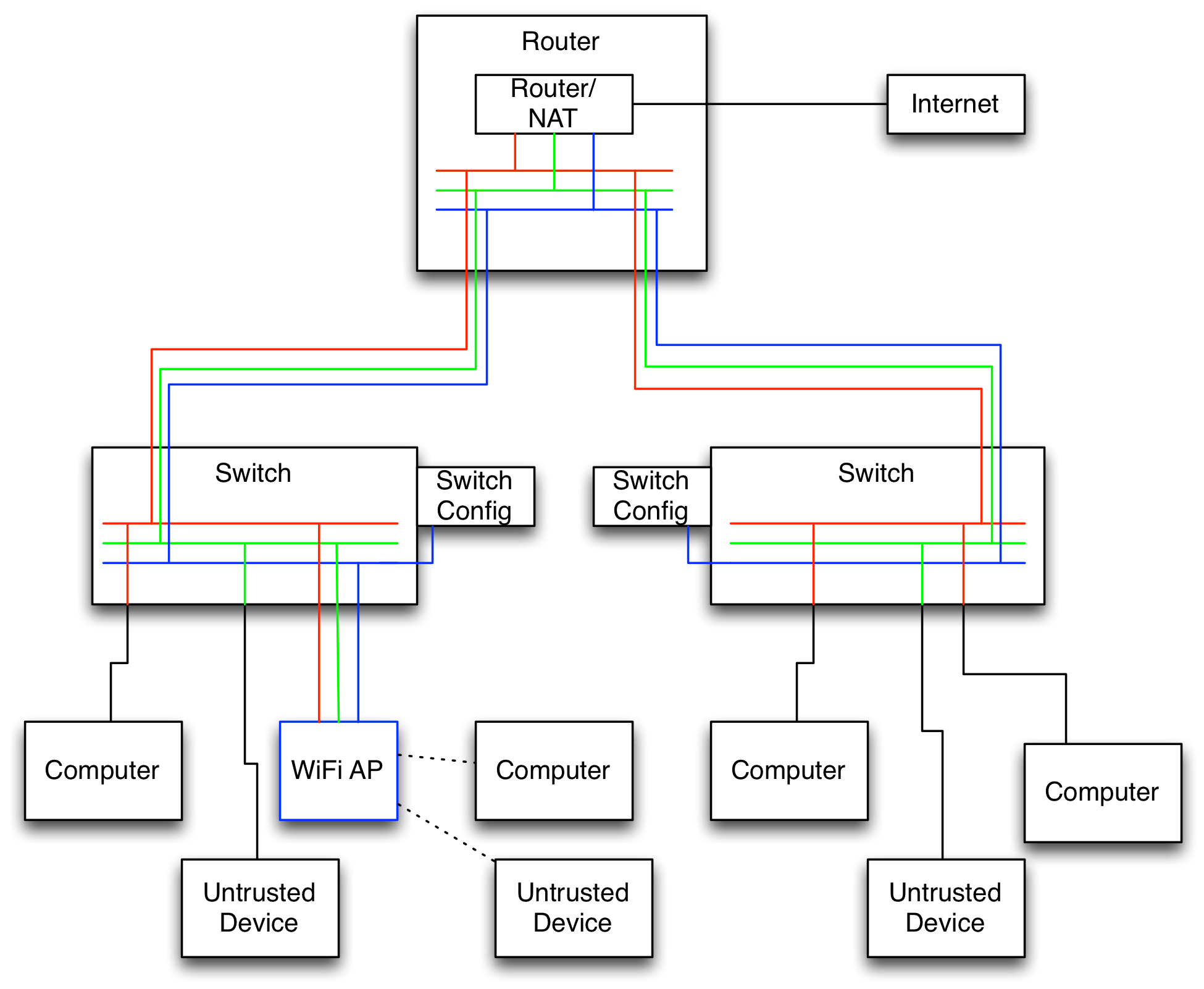
Generally I separate my network cables into groups of tagged and untagged. The tagged cables are shown in colors indicating the networks passing on those cables and the untagged cables are black. The tagged cables only connect VLAN capable devices. Essentially this boils down to the cables running between my router, switches, and WiFi APs are tagged and all others are not. Notice the cable from a switch to a computer changes color from red to black. This port is an “untagged” port on the switch meaning it strips any VLAN tags from the packet before sending it out. Incoming packets are then tagged with the red network. Finally I turned on enforcement of VLANs on all ports to ensure this protection cannot be bypassed. Notice that the blue network only connects the switch configuration and the AP.
Wireless Separation
The AP I use is a Ubiquiti Unifi UAP‑AC‑PRO which can advertise up to 4 networks per radio band and can assign each to a different VLAN. So I can have it advertise the red and green networks as different names. This allows me to have a mixture of trusted and untrusted devices on the wireless. I could put an iPhone on the trusted network but a Chromecast on the untrusted network.
Router Setup
This is the step that requires the most work. I’ll outline the command-line for each step as it’s easy to see the WebUI steps from the command-line and it is more compact. Most of this is the same as the default NAT setup with each step repeated 3 times. First is the setup on the individual network bridges:
/interface bridge
add name=v11
add name=v12
add name=v13
Next is the naming of the ports and setting up VLAN ports:
/interface ethernet
set [ find default-name=ether1 ] name=1-gateway
set [ find default-name=ether2 ] name=2-office
set [ find default-name=ether3 ] name=3-tv
set [ find default-name=ether4 ] name=4-master-bedroom
set [ find default-name=ether5 ] name=5-second-bedroom
/interface vlan
add interface=2-office name=2-office-v11 vlan-id=11
add interface=2-office name=2-office-v12 vlan-id=12
add interface=2-office name=2-office-v13 vlan-id=13
add interface=3-tv name=3-tv-v11 vlan-id=11
add interface=3-tv name=3-tv-v12 vlan-id=12
add interface=3-tv name=3-tv-v13 vlan-id=13
(notice I did not create vlan ports for the two bedrooms. In this example, these only contain trusted, red/12, devices).
Now add the ports to the bridges:
/interface bridge port
add bridge=v11 interface=2-office-v11
add bridge=v12 interface=2-office-v12
add bridge=v13 interface=2-office-v13
add bridge=v11 interface=3-tv-v11
add bridge=v12 interface=3-tv-v12
add bridge=v13 interface=3-tv-v13
add bridge=v12 interface=4-master-bedroom
add bridge=v12 interface=5-second-bedroom
Next is to setup the IP ranges and DHCP:
/ip pool
add name=v11 ranges=192.168.11.50-192.168.11.200
add name=v12 ranges=192.168.12.50-192.168.12.200
add name=v13 ranges=192.168.13.50-192.168.13.200
/ip dhcp-server
add address-pool=v11 disabled=no interface=v11 lease-time=18h name=v11
add address-pool=v12 disabled=no interface=v12 lease-time=18h name=v12
add address-pool=v13 disabled=no interface=v13 lease-time=18h name=v13
/ip address
add address=192.168.11.1/24 comment="Network Equipment Network" interface=v11 network=192.168.11.0
add address=192.168.12.1/24 comment="Private Network" interface=v12 network=192.168.12.0
add address=192.168.13.1/24 comment="Public Network" interface=v13 network=192.168.13.0
/ip dhcp-server network
add address=192.168.11.0/24 dns-server=192.168.11.1 gateway=192.168.11.1 netmask=24
add address=192.168.12.0/24 dns-server=192.168.12.1 gateway=192.168.12.1 netmask=24
add address=192.168.13.0/24 dns-server=192.168.13.1 gateway=192.168.13.1 netmask=24
Finally comes the standard firewall rules:
/ip firewall filter
add action=accept chain=input comment=Established connection-state=established log-prefix=""
add action=accept chain=input comment=Related connection-state=related log-prefix=""
add action=drop chain=input comment="Drop everything else" in-interface=1-gateway log-prefix=""
add action=accept chain=forward comment=Established connection-state=established log-prefix=""
add action=accept chain=forward comment=Related connection-state=related log-prefix=""
add action=drop chain=forward comment=Invalid connection-state=invalid log-prefix=""
And the NAT rules (essentially the normal setup duplicated 3 times):
/ip firewall nat
add action=masquerade chain=srcnat comment="Network Equipment Network" \
    log-prefix="" out-interface=1-gateway src-address=192.168.11.0/24
add action=masquerade chain=srcnat comment="Private Network" log-prefix="" \
    out-interface=1-gateway src-address=1192.168.12.0/24
add action=masquerade chain=srcnat comment="Public Network" log-prefix="" \
    out-interface=1-gateway src-address=1192.168.13.0/24
/ip firewall filter
add action=accept chain=forward comment=External dst-address=!192.168.0.0/16 \
    log-prefix="" src-address=192.168.0.0/16
Lastly, if you stop here, be sure to put in:
/ip firewall filter
add action=drop chain=forward comment="Drop Everything Else" log-prefix=""
Working across subnets
This is easily the part where I spent the most time. Even though my devices are spread across different networks, I wanted things to behave as if they weren’t from a feature standpoint. For example, I wanted my Roku stuck on the untrusted network to be able to access my Plex Media Server on the trusted network, but nothing else there. Additionally I’d like a computer to be able to AirPlay to the receiver on the untrusted network.
The first step is to put everything of interest, such as AirPlay receivers, Plex Media Servers, etc… on static leases. So go into the DHCP config and look at the leases and make each one of interest static. Then certain operations such as AirPlay need Bonjour to work across subnets. Bonjour is explicitly designed to not do this, so we need another solution. I used a Raspberry Pi running Raspbian that I connected to a tagged port on a switch with VLANs 12 and 13. I then setup these VLANs on the Pi’s ethernet interface. On it I ran sudo apt-get install avahi-daemon and edited /etc/avahi/avahi-daemon.conf and uncommented the second line:
[reflector]
enable-reflector=yes
This enables avahi, the Bonjour daemon on Raspbian, to receive a Bonjour broadcast on one interface and re-broadcast it on the other interfaces. With this, the AirPlay broadcasts from the receiver now make it to the trusted network. Next is to setup firewall rules to allow the communication:
To expose Plex Media Server to other networks:
/ip firewall filter
add action=accept chain=forward comment="PMS on Server" dst-address=192.168.12.5 \
    dst-port=32400 log-prefix="" protocol=tcp
To use airplay on 192.168.13.7:
/ip firewall filter
add action=accept chain=forward comment="Receiver Airplay UDP transport" \
    dst-address=192.168.12.0/24 log-prefix="" protocol=udp src-address=192.168.13.7
add action=accept chain=forward comment="Receiver Airplay and remote" \
    dst-address=192.168.13.7 log-prefix="" src-address=192.168.12.0/24
For UniFi APs to communicate with setup server at 192.168.12.123:
/ip firewall filter
add action=accept chain=forward comment="UniFi Management" dst-address=\
    192.168.11.0/24 log-prefix="" src-address=192.168.12.123
add action=accept chain=forward comment="UniFi Network Reachback" \
    dst-address=192.168.12.123 log-prefix="" src-address=192.168.11.0/24
/ip dhcp-server option
add code=43 name=unifi value=0x0104C0A80C7B
The 0x0104C0A80C7B is 0x0104 followed by the hex representation of 192.168.12.123. Then, in /ip dhcp-server network add the dhcp-option=unifi to the 192.168.11.0 network. This allows Ubiquiti network hardware to find the setup server.
For trusted computer 192.168.12.56 to configure network devices. Note this rule is disabled normally and only enabled for the time necessary to do the configuration and then disabled again:
/ip firewall filter
add action=accept chain=forward comment="Network Management" disabled=yes \
    dst-address=192.168.11.0/24 log-prefix="" src-address=192.168.12.56
And finally the catch-all rule at the end:
/ip firewall filter
add action=drop chain=forward comment="Drop Everything Else" log-prefix=""
That’s essentially my network setup at home. Numbers have been changed to protect innocent devices, but you should get a general understanding of the setup. I realize this is not a simple setup but I know a lot of technical people read my blog and this is likely to be of use to them. I expect that in the near future we will start to see wireless routers have these features built-in as we see an increase in the exploitation of consumer devices.